Instruction Decoder, instruction registerindeki komutu çözüp buna göre işlemci içindeki modülleri konfigüre edip komutun yürütülmesini sağlar. Kontrol edilen sinyallerin açıklamaları için önceki yazılara bakılabilir. Tasarımın VHDL kodu aşağıdadır.
library IEEE;
use IEEE.STD_LOGIC_1164.ALL;

entity Instruction_Decoder is
    port(Instruction_In : in std_logic_vector(15 downto 0); --Komut girişi
        Flags_In : in std_logic_vector(1 downto 0);          --Bayrak girişleri

        --Register kontrol çıkışları
        Enable : out std_logic;
        Rn, Rm : out std_logic_vector(2 downto 0);
        Rd : out std_logic_vector(2 downto 0);

        --ALU kontrol çıkışları
        ALU_Operations : out std_logic;
        Arithmetical_Operations : out std_logic_vector(1 downto 0);
        Logic_Operations : out std_logic_vector(1 downto 0);
        Flags_Update : out std_logic;

        --PC kontrol çıkışları
        Branch : out std_logic_vector(1 downto 0);

        --Veri yolu kontrol çıkışları
        ALU_Mux : out std_logic;
        ALU_Zero_Mux : out std_logic;
        Return_Mux : out std_logic;

        --Diğer kontrol çıkışları
        R_W : out std_logic;
        Bus_Active : out std_logic;
        Im_Data_Out : out std_logic_vector(7 downto 0));


end Instruction_Decoder;

architecture Behavioral of Instruction_Decoder is

begin

--Her bir komut için kontrol çıkışları tek tek ayarlanır.
    process(Instruction_In)
    begin
        --MOV
        if Instruction_In(15) = '0' then
            Rd <= Instruction_In(13 downto 11);
            Rm <= Instruction_In(6 downto 4);
            Im_Data_Out <= Instruction_In(10 downto 3);
            Enable <= '1';
            ALU_Mux <= Instruction_In(14);
            ALU_Zero_Mux <= '1';
            ALU_Operations <= '0';
            Arithmetical_Operations <= "00";
            Return_Mux <= '0';
            Flags_Update <= '0';
            R_W <= '0';
            Bus_Active <= '0';
            Branch <= "00";
        --MOV

        --ADD, ADC, SUB
        elsif Instruction_In(15 downto 14) = "10" then
            Rd <= Instruction_In(10 downto 8);
            Rn <= Instruction_In(7 downto 5);
            Rm <= Instruction_In(4 downto 2);
            Im_Data_Out <= "000" & Instruction_In(4 downto 0);
            Enable <= '1';
            ALU_Mux <= Instruction_In(13);
            ALU_Zero_Mux <= '0';
            ALU_Operations <= '0';
            Arithmetical_Operations <= Instruction_In(12 downto 11);
            Return_Mux <= '0';
            Flags_Update <= '1';
            R_W <= '0';
            Bus_Active <= '0';
            Branch <= "00";
        --ADD, ADC, SUB

        --AND, OR, NOT
        elsif Instruction_In(15 downto 13) = "110" then
            Rd <= Instruction_In(9 downto 7);
            Rn <= Instruction_In(6 downto 4);
            Rm <= Instruction_In(3 downto 1);
            Im_Data_Out    <= "0000" & Instruction_In(3 downto 0);
            Enable <= '1';
            ALU_Mux <= Instruction_In(12);
            ALU_Zero_Mux <= '0';
            ALU_Operations <= '1';
            Logic_Operations <= Instruction_In(11 downto 10);
            Return_Mux <= '0';
            Flags_Update <= '1';
            R_W <= '0';
            Bus_Active <= '0';
            Branch <= "00";
        --AND, OR, NOT

        --CMP, CMN
        elsif Instruction_In(15 downto 12) = "1110" then
            Rn <= Instruction_In(9  downto 7);
            Rm <= Instruction_In(6 downto 4);
            Im_Data_Out <= "0" & Instruction_In(6 downto 0);
            Enable <= '0';
            ALU_Mux <= Instruction_In(11);
            ALU_Zero_Mux <= '0';
            ALU_Operations <= '0';
            Arithmetical_Operations <= (not Instruction_In(10)) & '0';
            Flags_Update <= '1';
            R_W <= '0';
            Bus_Active <= '0';
            Branch <= "00";
        --CMP, CMN

        --LDR, STR
        elsif Instruction_In(15 downto 11) = "11110" then
            Rn <= Instruction_In(6 downto 4);
            Rm <= Instruction_In(9 downto 7);
            Rd <= Instruction_In(9 downto 7);
            Im_Data_Out <= "0000" & Instruction_In(3 downto 0);
            Enable <= Instruction_In(10);
            ALU_Mux <= '1';
            ALU_Zero_Mux <= '0';
            ALU_Operations <= '0';
            Arithmetical_Operations <= "00";
            Return_Mux <= '1';
            Flags_Update <= '0';
            R_W <= Instruction_In(10);
            Bus_Active <= '1';
            Branch <= "00";
        --LDR, STR

        --B
        elsif Instruction_In(15 downto 10) = "111110" then
            Im_Data_Out <= Instruction_In(7 downto 0);
            Enable <= '0';
            Flags_Update <= '0';
            R_W <= '0';
            Bus_Active <= '0';
            Branch <= '0' & (((not Instruction_In(8)) and (not Instruction_In(9))) or (Instruction_In(8) and Flags_In(1)) or (Instruction_In(9) and (not Flags_In(1))));
        --B

        end if;
    end process;

end Behavioral;
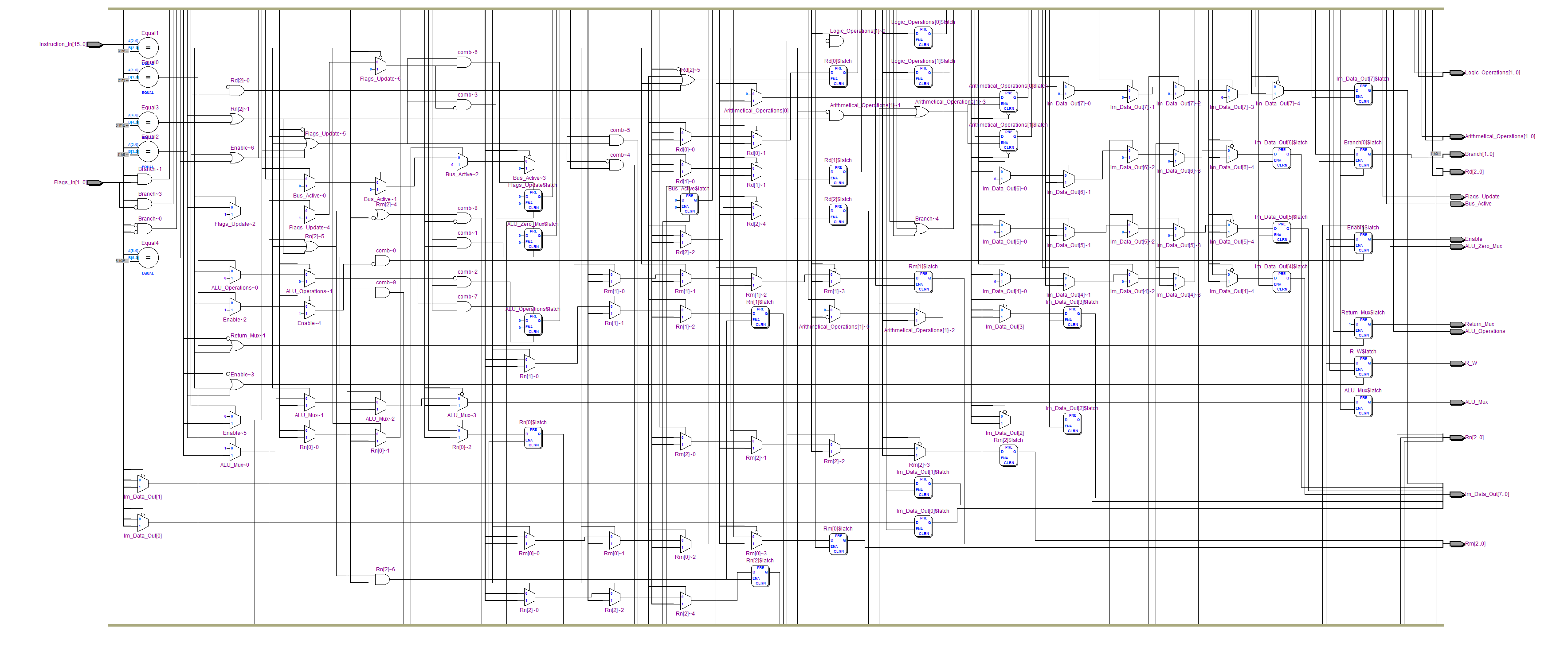
Quartus II programının oluşturduğu RTL şeması: