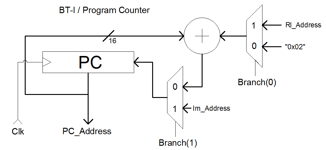
Program counter yani program sayacı, yürütülecek komutun ROM üzerindeki adresini taşır. Her bir cycle'da değeri komut seti uzunluğu olan 2 Byte kadar artar. Tasarımı şu şekildedir:
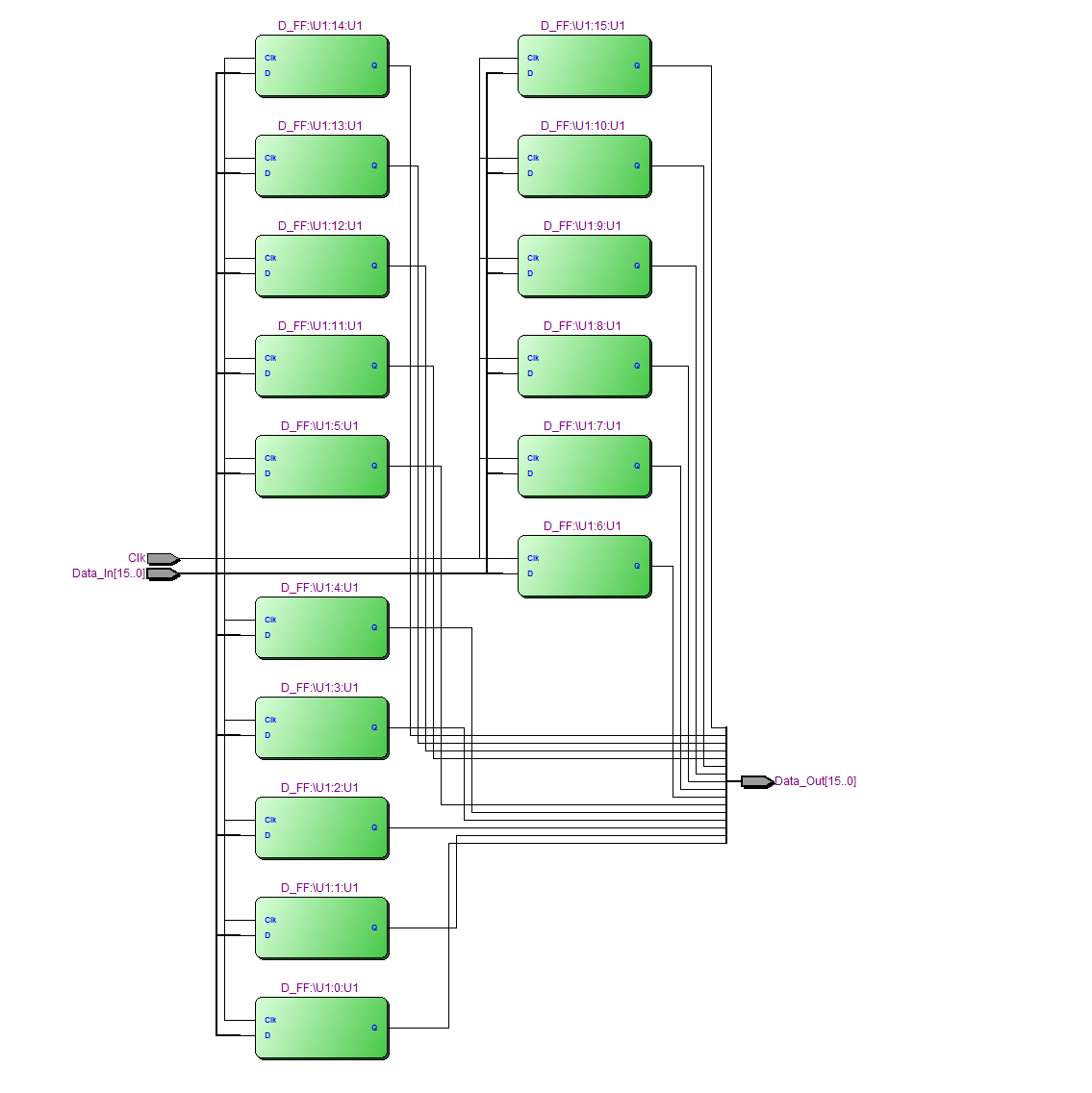
 PC: Program counter registeri. 16 tane D tipi flip-flop'tan oluşur. VHDL kodu şu şekildedir:
D tipi Flip-Flop:
library IEEE;
use IEEE.STD_LOGIC_1164.ALL;

entity D_FF is
    PORT(Clk : in std_logic; --Clock girişi
        D : in std_logic;    --Data girişi
        Q :out std_logic);   --Data çıkışı
end D_FF;

architecture Behavioral of D_FF is

    signal QSignal : std_logic := '0';

begin
        process(Clk)
        begin
            if rising_edge(Clk) then --Clockun yükselen kenarı ile
                QSignal <= D;        --Data girişindeki veriyi QSignal'e at
            end if;
        end process;

        Q <= QSignal;    --QSignal'i Data çıkışına bağla
end Behavioral;
PC Registeri:
library IEEE;
use IEEE.STD_LOGIC_1164.ALL;

entity PC_Register is
    PORT(Clk : in std_logic;                            --Clock sinyali
        Data_In : in std_logic_vector(15 downto 0);     --Data girişi
        Data_Out : out std_logic_vector(15 downto 0));  --Data çıkışı
end PC_Register;


architecture Behavioral of PC_Register is

--Komponent tanımlaması
component D_FF
    PORT(Clk : in std_logic;
        D : in std_logic;
        Q :out std_logic);
end component;

begin
--16 tane D tipi Flip-Flop u paralel şekilde bağla
            U1 : for i in 0 to 15 generate
                U1 : D_FF PORT MAP(Clk, Data_In(i), Data_Out(i));
            end generate;
end Behavioral;
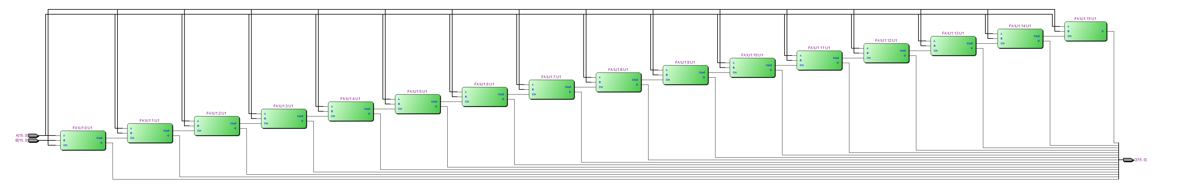
Toplayıcı: 16 tane Full-Adder'dan oluşur. VHDL kodu şu şekildedir:
Full-Adder:
library IEEE;
use IEEE.STD_LOGIC_1164.ALL;

entity FA is
    port(A, B, Cin : in std_logic; --Girişler
        O, Cout : out std_logic);  --Çıkışlar
end FA;

architecture Behavioral of FA is
    signal AxorB : std_logic;
begin
--Tam toplayıcı
    AxorB <= A xor B;
    O <= AxorB xor Cin;
    Cout <= (A and B) or (AxorB and Cin);
end Behavioral;
16-Bitlik toplayıcı:
library IEEE;
use IEEE.STD_LOGIC_1164.ALL;

entity Adder_16 is
    port(A, B : in std_logic_vector(15 downto 0); --16 bitlik girişler
        O : out std_logic_vector(15 downto 0));   --Çıkış
end Adder_16;

architecture Behavioral of Adder_16 is

--Komponent tanımlaması
component FA
    port(A, B, Cin : in std_logic;
        O, Cout : out std_logic);
end component;

--Elde sinyalleri
    signal Carry : std_logic_vector(16 downto 0) := (others => '0');

begin
--Full-Adder ların birleştirilmesi
        U1: for i in 0 to 15 generate
            U1 : FA PORT MAP(A(i), B(i), Carry(i), O(i), Carry((i + 1)));
        end generate;

--Toplamanın işaretli olabilmesi için B sinyalinin işaret biti
--toplayıcının elde girişine bağlanır. Bu sayede "1...." şeklinde
--bir sinyal girdiğinde çıkarma işlemi yapılır.
        Carry(0) <= B(15);

end Behavioral;
Modüllerin birleştirilmesi:
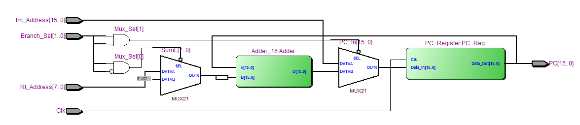
library IEEE;
use IEEE.STD_LOGIC_1164.ALL;

entity Program_Counter is
    PORT(Clk : in std_logic;                           --Clock girişi
        Rl_Address : in std_logic_vector(7 downto 0);  --Relatif adres girişi
        Im_Address : in std_logic_vector(15 downto 0); --Direkt adres girişi
        Branch_Sel : in std_logic_vector(1 downto 0);  --Dallanma seçimi girişi
        PC : out std_logic_vector(15 downto 0));       --Program adresi çıkışı
end Program_Counter;


architecture Behavioral of Program_Counter is

--Komponent tanımlamaları
component PC_Register
    PORT(Clk : in std_logic;
        Data_In : in std_logic_vector(15 downto 0);
        Data_Out : out std_logic_vector(15 downto 0));
end component;

component Adder_16
    PORT(A, B : in std_logic_vector(15 downto 0);
        O : out std_logic_vector(15 downto 0));
end component;

    signal PC_In : std_logic_vector(15 downto 0);
    signal PC_Out : std_logic_vector(15 downto 0);
    signal PC_Sum_Out : std_logic_vector(15 downto 0);
    signal SumL : std_logic_vector(7 downto 0);
    signal SumH : std_logic_vector(7 downto 0);
    signal Mux_Sel : std_logic_vector(1 downto 0);

begin
--PC registerinin oluşturulması
    PC_Reg : PC_Register
        PORT MAP(Clk, PC_In, PC_Out);

--Toplayıcı modülün oluşturulması
    Adder : Adder_16
        PORT MAP(PC_Out, SumH & SumL, PC_Sum_Out);

--Relatif adres ile X"02" arasında seçim yapan mux
    with Mux_Sel(0) select
        SumL <= X"02" when '0',
                  Rl_Address when others;

--Relatif adrese gelen direkt veri 8 bitlik olduğundan
--bu verinin toplayıcı için 16 bitlik veriye dönüştürülmesi
--gerekir. Burada direkt verinin 7. bitinin değeri, 8-15 bitlerine
--aktarılır.
    U1 : for i in 0 to 7 generate
        SumH(i) <= SumL(7);
    end generate;

--Direkt dallanma için seçim yapan mux
    with Mux_Sel(1) select
        PC_In <= PC_Sum_Out when '0',
                    Im_Address when others;

    PC <= PC_Out;

    Mux_Sel(0) <= Branch_Sel(0) and (not Branch_Sel(1));
    Mux_Sel(1) <= Branch_Sel(0) and Branch_Sel(1);

end Behavioral;
Aşağıda Quartus II programının oluşturduğu RTL modelleri görülmektedir: